

3D Weld Inspection System
![]()
POLASTAR is the brand name of CORETEC’s 3D inspection system.
Welding visual inspection goes from visual inspection to automation
The trend of visual inspection is already moving from visual inspection to automation using inspection equipment. Behind this are “situation that does not depend on humans”, “requests for quality visualization”, “traceability requirements” and so on. The same applies to welding inspections. Coretec’s 3D welding inspection system uses an inspection system (robot, camera and software) on the production line to perform speedy and accurate automatic operations from scanning to 3D analysis and pass/fail judgment.
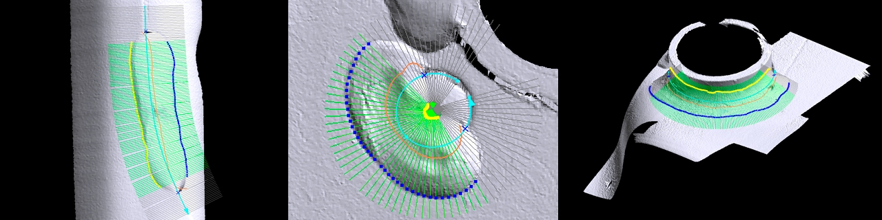
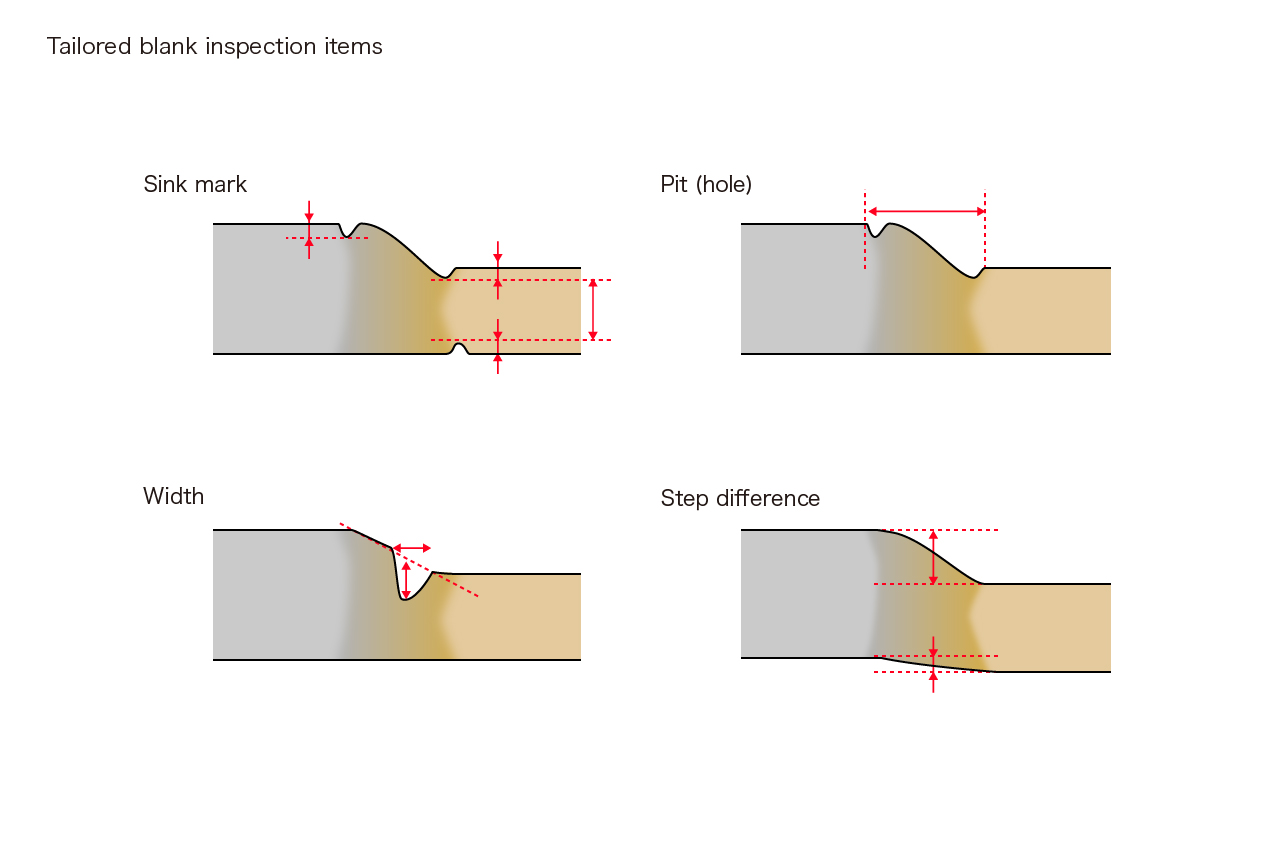
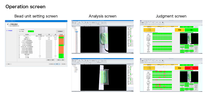
Automatic inspection procedure image view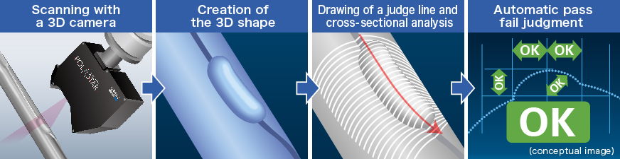 Cross-section analysis drawings
Applications
It is suitable for welding visual inspection of products requiring high safety and important parts requiring traceability.《 Inspection target 》 An example : Car
Muffler
Side impact beam
Steel wheel
Shock absorber
Seat
Steering member
Exhaust manifold
Cross member
Suspension arm
Inspection welding type
Introduction example
Features
CORETEC’s unique innovative technology for realizing “Absolute Quality”
1. Accurate 3D shape creation for accurate analysis of welded parts
CORETEC’s “3D weld inspection system” constantly acquires robot coordinate information, making it possible to acquire accurate 3D shapes regardless of changes in the robot motion and posture. It can also easily superimpose multiple 3D shapes.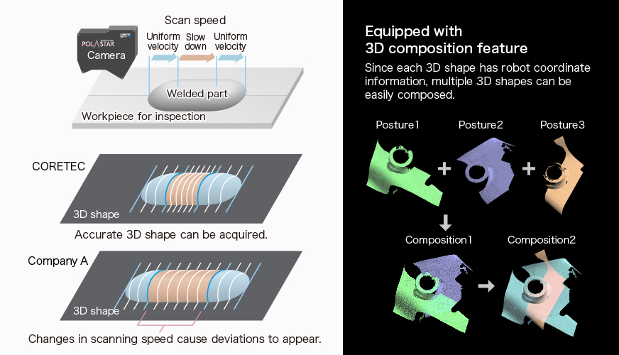
2. Patented analysis feature that doesn’t depend on scan direction Patent: No. 5758090
The “3D weld inspection system” conducts cross-sectional analysis by drawing a judge line after the 3D shape is acquired. Accordingly, since there is no need to accurately trace the welded part or force the robot to conduct complicated movements, merits such as easy teaching and shortened cycle time are realized.CORETEC’s “3D weld inspection system”
Since a judge line (route line) is drawn on after the 3D shape is acquired, analysis can be conducted on optional section lines. Teaching is also simple, regardless of the scan direction. The generated 3D shape is easy to recognize as it is the same as the actual shape.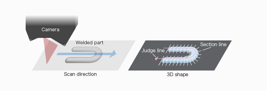
Company A’s inspection system (example)
Since the section lines are set during scanning, it is necessary to align the camera direction and posture with the route lines on the welded part, thus making the teaching more complicated. Moreover, if curves and spiral shapes are included, not only will the 3D shape differ from the actual shape, but scan time will be impacted.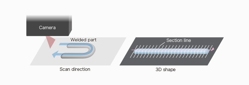
3. Fully selectable functions. Also supports traceability.
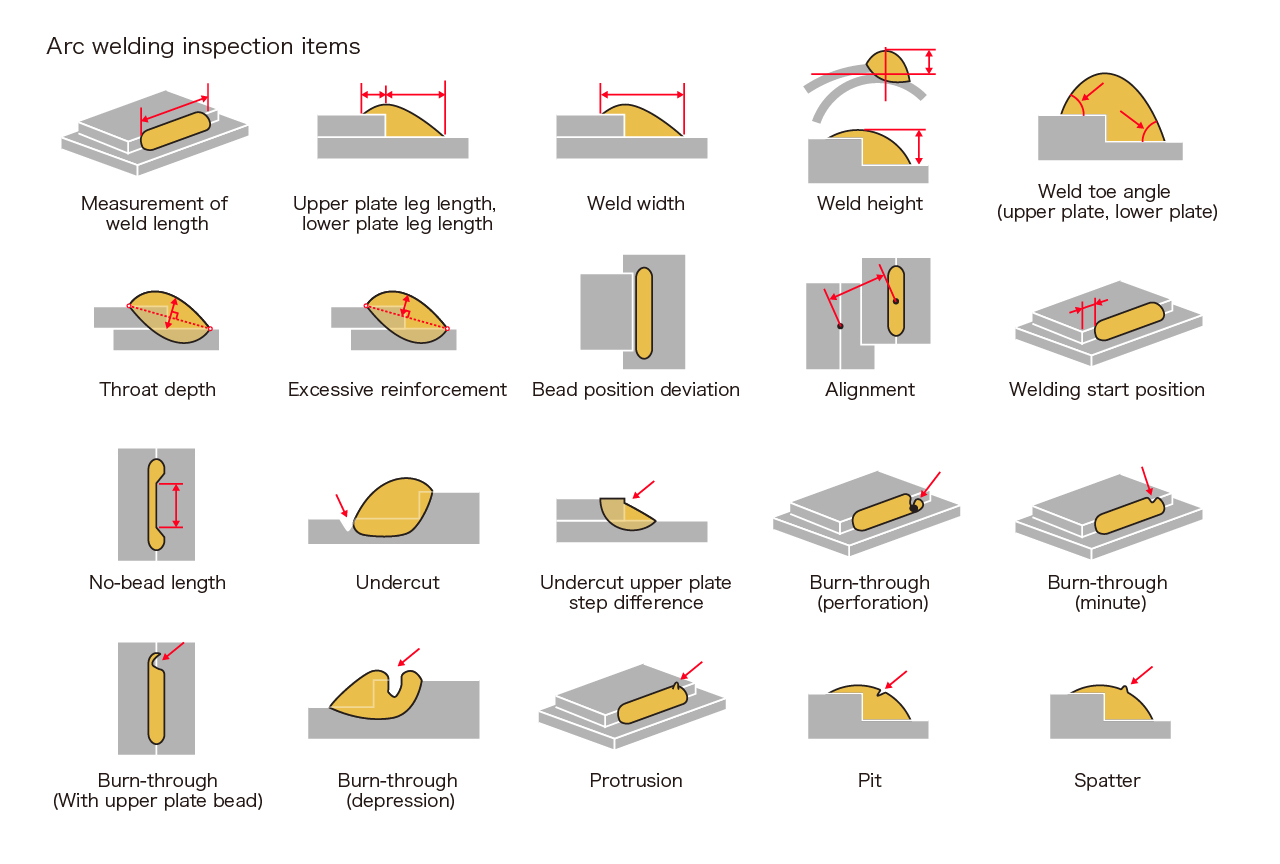
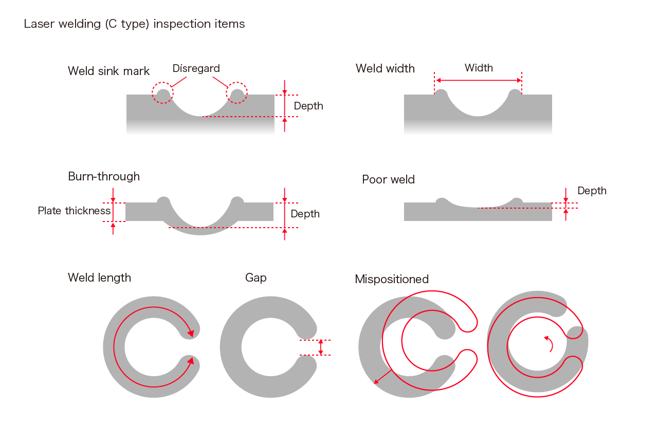
- There are more than 20 inspection items, such as leg length and weld length, enabling various needs to be responded to.
- Saving 3D shape data, CSV file output and simple data statistical processing are possible, enabling traceability requirements to also be met.
- User-friendly screen operations. With a diverse parameter setting feature, users can freely select judgment items.
4. Easy robot teaching
As mentioned above, the robot does not have to make complicated movements, and since it has a guide laser function, robot teaching time can be shortened.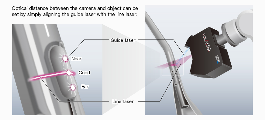
5. Compatible with major domestic robot manufacturers
Currently, we are able to share coordinate information with five robot manufacturers in Japan, and it is possible to utilize idle machines at the customer’s side.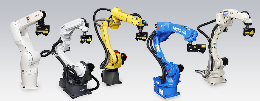
System Configuration
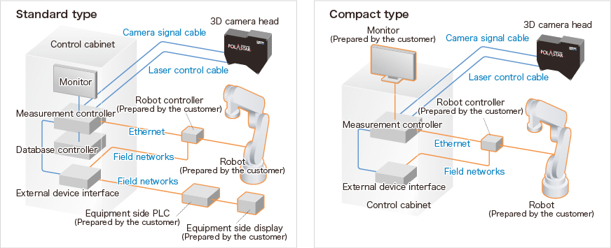 For details, see 3d_weld_inspection_system_model_list_en_02.pdf (PDF:380kB)
3D Camera Head Specifications
| Model | Measurement center distance | Measurement width | 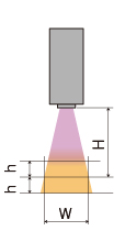 |
Distance resolution | Width resolution | Inspection speed | Laser class | Size | Weight |
|---|---|---|---|---|---|---|---|---|---|
| 0.3mm pitch | (D×H×W) | ||||||||
| H±h(mm) | W(mm) | (μm) | (μm) | (mm/sec) | (mm) | (kg) | |||
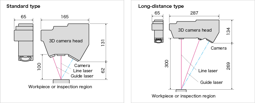
| CVS-13010C (standard) | 100±20 | 56~73 | 23 | 51 | 170 | Class2 | 65×131×165 | 1.1 | |
| CVS-13015C (high-accuracy) | 100±10 | 41~47 | 15 | 35 | 112 | Class2 | 65×131×165 | 1.1 | |
| CVS-13030C (long distance) | 300±20 | 62~68 | 24 | 51 | 170 | Class2 | 65×134×287 | 1.5 | |
| CVS-13030CR (long distance) | Class3R |
 For details, see 3d_camera_head_specifications_en_03.pdf (PDF:430kB)
Download Catalog “3D Weld Inspection System”
* Specifications are subject to change without prior notice.